Friday, November 22, 2013

Couple of the latest pictures

 
It is looking much more like a gocart.  Not too much missing in the engine compartment. 

 
The gauges are just temporarily mounted so that we could figure out the switches and buttons to mount.  eventually the dash will be covered in black vinyl or leather.

Radiator and fan shroud

I purchased the entire cooling system from a company called Breeze Automotive.  It is a small business that specializes in parts for Factory Five Roadsters.  The inlet and outlet radiator tubes are solid pieces.  If I were to get the parts from Factory Five they would have been corrugated aluminum.  I think the solid pieces and the other stuff put out by Breeze is a nice touch to the car.

 
The bare aluminum shroud without the hole for the fan.

 
Fan hole cutout.

 
Mocking up the radiator without the shroud.  I needed to see where the hoses would be, so I knew where to run the power steering lines, which I still haven't run.

 
Fan being installed on the shroud.  This is the outside, but it will never be seen since it will be pointed down.

 
This is the inside of the shroud.  It will REALLY never be seen.  The part in the upper left is a fan temperature control.  I need to stick the probe between the channels of the radiator when the shroud gets attached.  It had an adjustment knob on the outside.
 
The next steps are to make the power steering lines and install them.  Then, mount the shroud on the radiator and install the cooling system.  After that I will temporarily connect the gauges for the tach, water temp, oil pressure and voltage.  Then, pull the distributor so I can prime the oil pump and then reinstall it.  Then it will be time to start the engine for the first time.  Hopefully that will happen before the end of the year.

Sharon's Box

Since we decided to put a heater/defroster in the car, we don't have any room for a glovebox in the dash.  Even with the firewall forward mod, I would only be able to put in a 3/4" deep glovebox and we thought that would be useless.  Instead we are putting in a grab bar for the passenger to hold onto and a rear cubbyhole between the seats.  I initially said no to the rear cubbyhole, since I was going to have to build it from scratch and doubted my ability.  Sharon pretty much peer pressured me into trying to do it.  Well, I think it turned out awesome.  But, since it was her I idea, she gets the credit and also gets it referred to as "Sharon's box."


Here is the paperboard template.
 
 
Me bending one of the scrap aluminum pieces I dug up to make it from.  Notice the safety glasses and gloves. 


Looking from inside the trunk.  It is located where the battery was initially supposed to go.  But, since I decided to change everything and move the battery, I had room for the box.


From the front, still trying to figure it out.

 
Sharon also decided that she wanted to have it all pretty, so I had to make a trim ring for it too.

 
The bottom of the trim ring overlaps where the rear cockpit panel bends, so out came the mallet.  Hey, who is that balding guy in the picture?

 
The semi-finished product.  The whole thing was then disassembled and powder coated the same color as the engine compartment panels.  The back wall will be carpeted up to the trim ring.  I think it is going to look pretty sharp.

WTF - Wiring The Factory Five

 
 This is the Battery cutoff switch.  It will cutoff all power except power for the clock, GPS keep alive and maybe a constant power for the pushbutton start so it does not need as much time for bootup.  It will kill the engine in case of an emergency and also provide a little extra security against theft.

 
I soldered all of my lugs for the 6 AWG alternator cables, 4 AWG grounds and 2 AWG battery, starter and main grounds.  This was one of my first attempts.  I did not go too well.  I got much better at it and only had to redo a few lugs. 

 
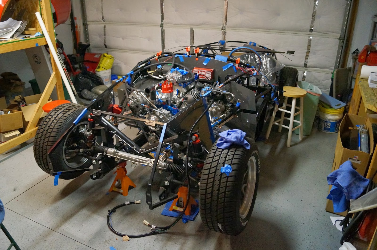
 This is the hole that I forgot to drill that prompted me to pull the engine back out.

 
Here is the main wiring harness before I modified it. 

 
Here it is after.  It may not look like much was done, but I had it torn all the way apart and modified a lot of it.

 
Inside the engine compartment nearing completion.  The upper right is where the rear harness had to come out of the footbox.  I joined it up with the alternator cables and in this picture the unwrapped starter cables.


Engine compartment almost done.  Here I was working on the wiring that came in the compartment from the passenger's side.  It has gauge, heater, wiper, choke and ignition wires.

 
Before I pulled the engine, the header was about 1/4" away from the footbox.  I was concerned that it would get the footbox too hot and damage the powdercoat.  I actually put a mod in to pull the footbox in and also installed some zero clearance insulation.

 
This is the starter wiring.  I have since changed the red cable out with one that has its lugs turned around.  That allowed the red cable lugs to go under the black cable lugs so that the red cable can move down towards the frame and away from the header that goes there.

Who's updating this thing anyway?

After the engine and transmission were installed I put most of the engine accessories on.  The next step was to start the wiring.  Since I was an electrician in a previous life, I was really looking forward to this part.  So, I pulled out the directions for the wiring harness and was ready to go.  I started out by seeing where all the harnesses were supposed to go.  Everything seemed ok until I read about the rear harness.  The instructions said to route the harness from the driver's side footbox out through the hole and then along the inside of the transmission tunnel.  I said "What hole?"  Well, I installed a firewall forward mod on the car, which moves the engine compartment side of the dash about 2 inches into the engine compartment.  This frees up room behind the dash for a heater and a glovebox.  It also makes you use a new inner driver's side footbox panel that they send you.  Guess what.  That panel they sent me, which is in the car already, didn't have a hole like the original one did.  Uh oh.  I needed to drill a 1 3/8" hole to put a grommet in and be able to pass the wires through.  The engine is about 4 inches away from the location of the hole.  I also found that the wiring for the starter relay was going to be a pain in the butt with the engine in.  Long story made longer is that I had to pull the engine and transmission out to be able to run all the wiring.  So, out it went.  It came out so fast (only took about 10 minutes) that no pictures were taken.  I think the photographer was busy with her kids or something.

Tuesday, April 23, 2013

Installing the Engine and Transmission

 The engine and transmission connected and ready to install.
 Adam Kropff, helper extraordinaire.  Kate photobombing.
 The plan was to lift the engine and transmission and then push the car into place.  Rachel's job was to steer and brake.  The car wound up being too low and we had to put it on stands and then move the engine.

 We should have used the front lift mount to give it a more radical angle.  Adam had to push down quite a bit to get the transmission under the firewall.


Four hours and ZERO scratches later.

Welding fun and prepping the engine.

 These are the braces that I welded up for the passenger's "Oh, Crap!" bar.
 With the braces installed and painted.  They look like they actually belong there.  It wasn't the prettiest welding, but I pushed and pulled on them with everything I had.  I thought I was going to pull the car off the jack stands and they did not budge.
 This is the spring from the power steering pump piston.  The pump is for a fox body Mustang and puts out a little too much pressure for the lighter roadster.  Cutting the spring lowers the power steering pressure and makes the car easier to drive.
 I welded on a small plate to the clutch pedal stop.  The pedal assembly is from a 2004 Mustang.  With my setup (having to pull out the stock clutch quadrant) the clutch pedal would be about 5 inches above the brake pedal.  This plate lowers the clutch pedal to where I like it.
My engine all dressed up.  I installed all the accessories while out of the car to make sure it all fit correctly and to figure out the belt length.  I pulled all that stuff back off before the engine install.

It's been a while..... BRAKE LINES!!! (The bane of my existance)

 This is a view from the master cylinder.  The silver sleeving over the brake line is thermal insulation.  The header is going to be only a few inches away in this area.  The insulation is supposed to protect up to 2000F radiant heat.  I also went with the highest temperature brake fluid I could find.
 This is the passenger brake line where it will pass below the radiator.
 Brake line running aft.  The larger line is the fuel line.
 Fuel and brake lines where they pass behind the driver's seat.
 Rear brake line passing under the trunk.
 Passenger rear line crossing over.
All of the brake lines before final installation.  It took me almost 2 months to get these lines the way I wanted them.  Most of them I did in one try, but I made a template for EVERY bend I did.  Practicing to see exactly where I needed to make the next bend.  Just like the fuel line, I found that the third dimension was really frustrating for me.  I'm still not 100% sure that they are perfectly leak tight.  If I ever talk about building another car, please remind me about the brake and fuel lines.